Home
Site Map
Source Page
The Air House - Power for the Engine Test Facilities
Flow charts and Diagrams
Click image for a larger view and extracts from the designer’s notes
written at the beginning of 1957
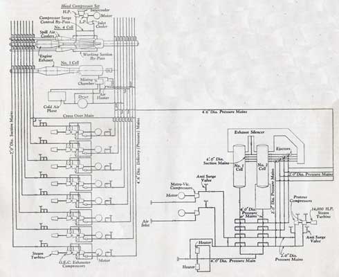
Left : Air flow distribution. Right : Layout of the altitude cell (Cell 3).
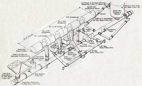
The suspension and support system for a GEC compressor. Schematic and artist’s impression.
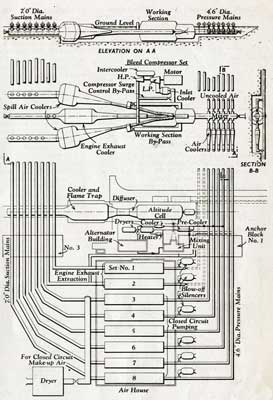
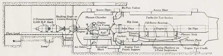
A section through the altitude cell.
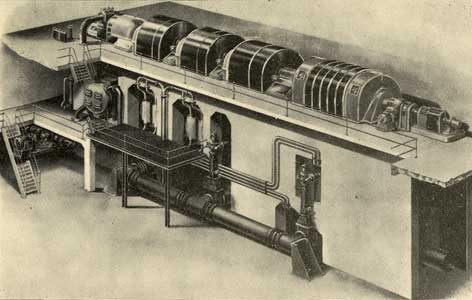
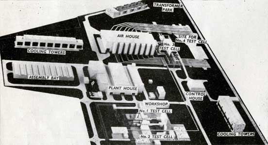
Left : A model of the engine test facility.
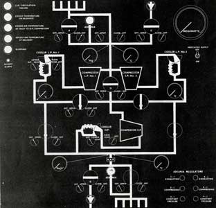
Right : The air control panel diagram for use of the plant controller.
Top